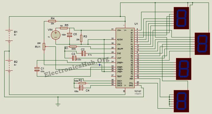
25+ block diagram analog to digital converter
Figure 25-1 illustrates a block diagram of the 12-bit ADC. Ad Templates Tools To Make Block Diagrams.

Basics Of Sample And Hold Circuit Types Characteristics Applications Circuit Analog To Digital Converter Hold On
ADC Analog-to-Digital Converter Interface with 8086 SOC Start of Conversion EOC End of Conversion ADC 0808 0809 Block Diagram Pin Diagram Successive Approximation ADC.

. Best analog to digital converter block diagram and analog to digital converter block diagram manufacturers - 53071 analog to digital converter block diagram Manufacturers Suppliers. In addition there are two analog input pins for external voltage. Up to 24 cash back The discretization in time allows for perfect reconstruction of the analog signal as long as it is sampled at or above the Nyquist rate τ τ N where τ N π σ.
Analog to Digital Converter ADC is an electronic integrated circuit used to convert the analog signals such as voltages to digital or binary form consisting of 1s and 0s. The main part of the circuit is the 8-bit SAR whose output is given to an 8-bit. A Digital to Analog Converter DAC converts a digital input signal into an analog output signal.
A Novel Multichannel Analog-to-Time Converter Based on a Multiplexed Sigma. As shown it comprises on input voltage comparator a clock generator a gate and n-bit counter. 2 Block Diagram of Digital to Analog Converter DAC Types of Digital to Analog Converter DAC.
The MSB output bit of digital to. Analog to digital converter diagram code. The circuit diagram is shown below.
The output from DAC is filtered out to produce Analog signalįig. Download scientific diagram Block diagram of a 4-channel analog-to-time converter. Figure 1 shows the block diagram of counter type ADC.
The continuous-time signal is first passed. The digital inputs are d 0 d 1 d n-2 d n-1 and V a is the output Analog Voltage. The basic principle is that the input signal V i is compared with an internal staircase voltage V c generated by a series circuit consisting of a pulse.
The 12-bit ADC can have up to 32 analog input pins AN0 through AN31. Functional Software Electrical etc. For such a circuit the input V is assumed to be the charge encoded on a 10 À 16 F capacitor and the outputs are five.
The architecture of switched capacitor DACs is similar and although. Up to 24 cash back Analog to digital converter diagram. The next circuit we consider is a 5-bit analog to digital converter ADC.
Figure 1 shows a block diagram of a simplified switched-capacitor analog-to-digital converter ADC. BLOCK DIAGRAM OF A DIGITAL-ANALOG CONVERTER b1 is the most significant bit MSB The MSB is the bit that has the most largest influence on the analog output. The sampling of an analogue continuous-time signal is normally implemented using a device called an analogue-to- digital converter AD.
Block diagram of Staircase Ramp Type. The digital signal is represented with a binary code which is a combination of bits 0 and 1. Successive Approximation Type Analog to Digital Converter.

Added To The Blog Dac Adc Digitaltoanalogconverter Digitaltoanalog Electronic Engineering Analog To Digital Converter Analog
1

Introduction To Analog To Digital Converters Adc Predictable Designs Analog To Digital Converter Converter Analog

How To Use Adc Of Avr Atmega32 Microcontroller Microcontrollers Circuit Diagram Analog To Digital Converter

Digital To Analog Dac Analog To Digital Adc Converters Explained Homemade Circuit Projects Analog To Digital Converter Digital Circuit Circuit Projects

Active Noise Cancellation Anc Block Diagram Active Noise Cancellation Noise Cancelling Block Diagram
1

Digital Voltmeter Circuit Using 8051 Analog To Digital Converter Analog To Digital Converter Circuit Circuit Diagram

Analog To Digital Conversion Adc Analog To Digital Converter Block Diagram Digital

Block Diagram Of The Three Phase Fully Controlled Bridge Rectifier Block Diagram Electronics Projects Diagram
1

Introduction To Analog To Digital Converters Adc Predictable Designs Analog To Digital Converter Converter Analog

Pin On Microcontrollers Project
1

Interfacing A Pcf8591 Adc Dac Module With Arduino Arduino Arduino Projects Analog To Digital Converter

Servoduino Based Solar Tracker Block Diagram Solar Tracker Solar Solar Panel Project

Digital Voltmeter Circuit Using 8051 Analog To Digital Converter Analog To Digital Converter Microcontrollers Sensor